MICROCHIP ICD4 REVIEW

[Mike] is an avid PIC developer and replaced his ICD3 debugger for an ICD4. He made a video with his impressions and you can see it below. [Mike] found the heavy aluminum case with a sexy LED attractive, but wondered why he was paying for that in a development tool. He was also unhappy that they replaced the ICD3 cable connections with new connectors. Finally, he wished for the pin out to be printed on the case.

On the other hand, the ICD4 will also do JTAG and handle the Atmel parts (which Microchip acquired). [Mike] opens the box and shows the inside of the device before actually using it for the intended task.

As you would expect, the ICD4 integrates well with MPLAB and does the same kind of functions you expected from the ICD3 and other Microchip programmer/debuggers. [Mike] found the programming algorithm was a little different from previous devices, so he put the scope on it and also compares the speed of programming between a PICKit3, an ICD3, and the ICD4.

ICD4 is a pretty serious tool. If you want to just experiment, you can build your own PIC programmers or try the PICKit 3. You can also pick up a cheap board and go the online IDE route.

Microchip – Next-generation in-circuit debugger offers unparalleled speed and flexibility

Microchip has announced the MPLAB ICD 4, an in-circuit programming and debugging development tool for Microchip’s PIC microcontroller and dsPIC digital signal controller portfolios. The device includes all the features of the popular MPLAB ICD 3 debugger while adding increased speed through a faster processor and increased RAM.

Microchip

The device’s significant improvement in speed is accomplished through a 32-bit MCU running at 300MHz. Faster processing, together with an increased buffer memory of 2MB, results in a product that is up to twice as fast as its predecessor.

Also Read: How to Connect the PIC Microcontroller

The puck-shaped unit is housed in a durable, black case with a brushed aluminum top and is accented with an LED light strip to indicate debugging status.

The device is easy to use and supports all PIC microcontrollers and dsPIC digital signal controllers in the company’s portfolio through the MPLAB X IDE. This simplifies the design process for customers when they choose to migrate from one PIC MCU to another to meet the needs of their application.

How to Connect the PIC Microcontroller

Ok, so you have now got your programmer, and you have a PIC or two. It is all very well knowing how to program the PIC in theory, but the real learning comes when you try your code on a PIC and see the results yourself in a circuit. – Microcontroller

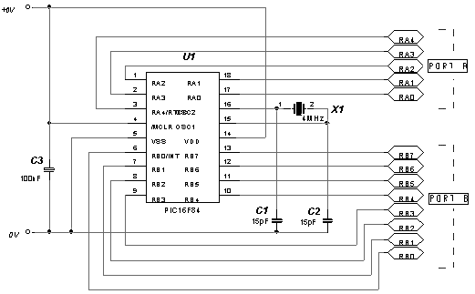
You could build a circuit each time and program the PIC to see if the program works, or you can make yourself a development board. A development board allows you to simulate the environment around the PIC. We have included a circuit diagram to show a very basic and cheap development board. You can, of course add LEDs and switches to this, but We have included the bare bones. You can monitor the Input/Output pins by connecting LEDs directly to the pins, and they will light up when the pins go high. Also, you can add switches to the pins, so that you can select which inputs are high, and which are low. Basically, what We are saying is if you start with this circuit, you can add whatever you feel necessary.

How to Connect the PIC Microcontroller

We will run through the circuit diagram, which We admit isn’t much, but it will give you a feel of things to come.

The supply rail is set to +6V, which is the maximum voltage of the PIC. You can use any voltage below this right down to +2V. C3 is known as a ‘Bypass’ Capacitor. All C3 does is reduce any noise on the supply rail. X1 is a 4MHz crystal. You could use a parallel resistor and capacitor circuit, but the cost of the crystal is negligible, and it is more stable. C1 and C2 help reduce any stray oscillations across the crystal, and get rid of any unwanted noise etc before the signal goes into the PIC.

X10 Speech Recognition Interface

X-10 is an international technology that provides an easy method of creating home automation. Marry this technology with a speech recognition circuit and the user can use verbal commands to activated electrical appliances and lights around the home or apartment. If this is of interest to you then read on. – Microcontroller

The X-10 Interface circuit will allow you to control up to 16 appliance control modules on any of the sixteen available X-10 house codes using the SR-07 speech recognition circuit. The SR-07 speech recognition circuit has its own construction article here and that information will not be repeated here. You may purchase the speech recognition circuit in a kit form (SR-06), or a fully assembled and tested circuit (SR-07) from Images SI Inc., see parts list. The X-10 speech interface requires the speech recognition circuit to function. The speech recognition circuit is the front end of the system.

The speech recognition circuit and components are NOT rated for medical use, critical care or when the possibility of a non-functioning or non-recognized command may cause damage, personal injury or put anyone or thing in jeopardy.

X-10 Technology

X-10 technology has been in the United States since 1978, introduced into our country by Sears and Radio-Shack. It uses the home’s household wiring (power grid) that powers electrical appliances to transmit and receive control commands to the appliances. There are a variety of X-10 commands at our disposal that include; on, off, dim/bright, all on, all off, etc., see table below. Our X-10 speech interface will issue only the basic on and off commands.

X10 Speech Recognition Interface 1

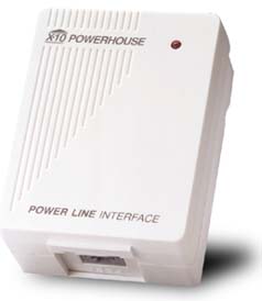
It appears that Radio-Shack no longer is carrying X-10 hardware. No matter, X-10 has many distributors including Amazon.com and Images SI Inc. You can also purchase X10 hardware from the official X10 site at http://www.x10.com/automation/index.html. There is a dizzying array of X10 components available. You require two X-10 components, the PL-513 Power Line interface, see figure 1 and at least one appliance controller AMC486 see figure 2. If you wish to run more than one appliance, you would need an equal number of appliances.
X10 Speech Recognition Interface 2


X-10 Command Codes


Code              Function Description
0 0 0 0 1        All Units Off Switch off all devices
0 0 0 1 1        All Lights On Switches on all lighting devices
0 0 1 0 1        On Switches on a device
0 0 1 1 1        Off Switches off a device
0 1 0 0 1        Dim Reduces the light intensity
0 1 0 1 1        Bright Increases the light intensity
0 1 1 1 1        Extended Code Extension code
1 0 0 0 1        Hail Request Requests a response from the device(s)
1 0 0 1 1        Hail Acknowledge Response to the previous command
1 0 1 x 1        Pre-Set Dim Selection of two predefined levels of light intensity
1 1 0 1 1        Status is On Response indicating that the device is on
1 1 1 0 1        Status is Off Response indicating that the device is off

Also Check:

Aside from the commands, listed above, the X-10 signal protocol also consists of an address.

Hardcore Micros – Microchips PIC10F32x

As an embedded engineer I’m always looking for more and more functions from a smaller and smaller package. Over the last six months, Microchip has been releasing information about the smallest of its chips – PIC10F32x – and in this post I want to look at the new and interesting features coming to PICs. – Microcontroller

Hardcore Micros - Microchips PIC10F32x 1

Up till now when I have looked at the very small end of the micro range, the PIC10s have never offered anything that would get me excited or convince me that they are very usable. At ebmpapst, when I’m designing bottom-end tiny products, I need at least one PWM, so I have been using what I would have called a slightly overspec PIC12F615 for my products.

In the last few weeks however, Microchip has released the Data Sheet for the PIC10F320 and PIC10F322. These I have been looking at using for some time; however, it was the added features of these two new chips that stand out to me, and I’m not just talking about the added Flash and RAM or PWMs they now have.

The first new shiny feature is Configurable Logic Cells (CLC). The PIC10 is not the first to have these, as there is a new breed of PIC12s and 16s that have these too. However, having this and the other features on such a small chip is to me surprising and also powerful.

CLCs are chunks of combinational logic that can be configured to perform high-speed functions without needing core processing time. Each block has 8 inputs that can come from I/O pins, internal clocks, Peripherals, or even from register bits. These inputs can then be passed through one of a number of pre-configured logic blocks that perform functions like AND-OR, S-R, J-K and D type flip-flops. What’s then quite nice is that an external pin can be driven directly from this output, read internally, or it can even generate an interrupt. It may not have the flexibility and programmability of, say, a FPGA LAB, but I can see these becoming very useful glue logic tools for embedded engineers.

Another nice feature to find in such a small chip is the Complementary Waveform Generator (CWG). This allows you generate controllable waveforms for use in a half bridge or switching power supply for example. The module allows for selectable input sources and have some nice and simple auto-shutdown controls. Dead time is also programmable for both the rise and fall side. I’ve seen similar modules on the larger chips but found this much easier to understand and more independent of the code that may be running on the core.

Both the CLC and CWG could be really nice units if only you have a clock source that is easy to control and whose frequency is easy to set. Well the chips now also come with a Numerically Controlled Oscillator (NCO) that can be used to feed the above CLC and CWG modules. This is no Phase Lock Loop (PLL) but will allow for simple clock division. The module works by having a configured value added to an accumulator on each clock cycle. The overflow is then used as a raw output that can be used to drive the module in a number of modes. For example, simple toggling of the output allows for a fixed 50 percent duty, or you can use the module for pulsed frequencies with output pulse width control.

Hardcore Micros - Microchips PIC10F32x 6

The new features could very well be a clue to where Microchip is going with new designs, maybe trying out these features on the smaller silicon before it makes its way up to the 32bit cores. However, these new features are a welcome sight to me as an embedded engineer. I like the idea of getting more and more features inside small chips – my designs do not need a lot of I/O pins but they need to be clever. I really don’t want to be using a whopping big QFP just to get the features, but suffer with the high pin count.

Climate Controller Designed with PIC

The Sensirion SHT11 sensor is utilized by this climate controller in order to read the temperature and humidity measurements simultaneously.

Climate Controller Designed with PIC

The measurement and display scale of the climate controller can be selected between Centigrade and Fahrenheit as the temperature measurement ranges from -40° to 123°C and humidity is 0-100% temperature compensated. Some of the uses of this device include food dehydrating, hatchling warmer, small room temp/humidity control, and Greenhouse temperature/humidity control. – Microcontroller

Related:

The three distinct CD outputs with 10A load or 2DC outputs with one AC up to 4A are managed by the controller board. It also reads the sensor, switches the outputs, reads the rotary encoder, and updates the LCD display. The controller board can be used as a standalone device if temperature and humidity readings only are required.

The sensor uses the combined humidity and temperature sensor SHT11 from Sensirion which comes in a SMDpackage. It is designed from a double sided PCB so that the more obtainable and handy 8-pin DIP carrier version is allowed to be used. A 14-bit analog to digital converter is contained in the sensor for temperature conversion which results in a maximum resolution of 0.1°C.

Data Encryption Routines for PIC24 and dsPIC Devices

Introduction

Currently, there are three data encryption standards approved for use in the Federal Information Processing Standards (FIPS). This application note discusses the implementation of two of these for PIC24 and dsPIC30/33 devices: Triple Data Encryption Standard (TDES) and Advanced Encryption Standard (AES). – Microcontroller

TDES Encryption
Background
The original Data Encryption Standard (DES), a 64-bit block cipher, was invented in the early 1970s by IBM®. DES uses a 64-bit encryption key: 56 bits for encoding and decoding, the remainder for parity. It was adopted by the United States government in 1977 as standard for encrypting sensitive data. By the mid 1990s, several public organizations had demonstrated that they were able to crack a DES code within days.

Data Encryption Routines for PIC24 and dsPIC Devices

Triple DES (TDES) is a variant of DES, and is described in FIPS 46-2 and 46-3. TDES uses three cycles of DES to extend the key from 56 bits to 112 or 168 bits, depending on the mode of operation. Because of known weaknesses in the DES algorithm, the actual security is believed to be on the order of 80 and 112 bits, respectively, for the two different methods. The use of TDESwas suggested by the American government in 1999 for use in all systems, except in legacy systems, where only DES was available.

Related:

There are several different modes of TDES. The most common involves using two different keys. The data is encrypted with the first key. That result is then decrypted with the second key. The data is then finally encrypted once again with the first key. Other modes of operation include using three different keys, one for each of the stages, and encrypting in all rounds instead of decrypting during the second round. For most new applications, TDES has been replaced with Advanced Encryption Standard (AES). AES provides a slightly higher security level than TDES and is much faster and smaller in implementation than TDES.

The original DES algorithm is outlined in Figure 1. The cycle is run 32 times before the ciphertext is valid.

PIC Controlled Relay Driver

This circuit is a relay driver that is based on a PIC16F84A microcontroller. The board includes four relays so this lets us to control four distinct electrical devices. The controlled device may be a heater, a lamp, a computer or a motor. To use this board in the industrial area, the supply part is designed more attentively. To minimize the effects of the ac line noises, a 1:1 line filter transformer is used. – Microcontroller

Components
1 x PIC16F84A Microcontroller
1 × 220V/12V 3.6VA (or 3.2VA) PCB Type Transformer (EI 38/13.6)
1 x Line Filter (2×10mH 1:1 Transformer)
4 × 12V Relay (SPDT Type)
4 x BC141 NPN Transistor
5 × 2 Terminal PCB Terminal Block
4 × 1N4007 Diode
1 × 250V Varistor (20mm Diameter)
1 x PCB Fuse Holder
1 × 400mA Fuse
2 × 100nF/630V Unpolarized Capacitor
1 × 220uF/25V Electrolytic Capacitor
1 × 47uF/16V Electrolytic Capacitor
1 × 10uF/16V Electrolytic Capacitor
2 × 330nF/63V Unpolarized Capacitor
1 × 100nF/63V Unpolarized Capacitor
1 × 4MHz Crystal Oscillator
2 × 22pF Capacitor
1 × 18 Pin 2 Way IC Socket
4 × 820 Ohm 1/4W Resistor
1 × 1K 1/4W Resistor
1 × 4.7K 1/4W Resistor
1 × 7805 Voltage Regulator (TO220)
1 × 7812 Voltage Regulator (TO220)
1 × 1A Bridge Diode

PIC Controlled Relay Driver 1

The transformer is a 220V to 12V, 50Hz and 3.6VA PCB type transformer. The model seen in the photo is HRDiemen E3814056. Since it is encapsulated, the transformer is isolated from the external effects. A 250V 400mA glass fuse is used to protect the circuit from damage due to excessive current. A high power device which is connected to the same line may form unwanted high amplitude signals while turning on and off. To bypass this signal effects, a variable resistor (varistor) which has a 20mm diameter is paralelly connected to the input.

PIC Controlled Relay Driver 2

Controller schematic

Another protective component on the AC line is the line filter. It minimizes the noise of the line too. The connection type determines the common or differential mode filtering. The last components in the filtering part are the unpolarized 100nF 630V capacitors. When the frequency increases, the capacitive reactance (Xc) of the capacitor decreases so it has a important role in reducing the high frequency noise effects. To increase the performance, one is connected to the input and the other one is connected to the output of the filtering part.

PIC Controlled Relay Driver 3

Supply schematic

After the filtering part, a 1A bridge diode is connected to make a full wave rectification. A 2200 uF capacitor then stabilizes the rectified signal. The PIC controller schematic is given in the project file. It contains PIC16F84A microcontroller, NPN transistors, and SPDT type relays. When a relay is energised, it draws about 40mA. As it is seen on the schematic, the relays are connected to the RB0-RB3 pins of the PIC via BC141 transistors. When the transistor gets cut off, a reverse EMF may occur and the transistor may be defected.

Related:

To overcome this unwanted situation, 1N4007 diodes are connected between the supply and the transistor collectors. There are a few number of resistors in the circuit. They are all radially mounted. Example C and HEXcode files are included in the project file. It energizes the next relay after every five seconds.

To download the schematics, PCB layouts and the code files:
http://bit.ly/bFfbYh

Sinusoidal Control of PMSM Motors with dsPIC30F DSC

This application note describes a method of driving a sensored Permanent Magnet Synchronous Motor (PMSM) with sinusoidal currents controlled by a dsPIC30F Digital Signal Controller (DSC). The motor control firmware uses the dsPIC30F peripherals while the mathematical computations are performed by the DSP engine. The firmware is written in C language with some subroutines in assembly to take advantage of the special DSP operations of the dsPIC30F.– Microcontroller

Application Features

  • Sinusoidal current generation for controlling PMSM motor phases using Space Vector Modulation (SVM)
  • Synchronization of sinusoidal voltages to PMSM motor position
  • Four-quadrant operation allowing forward, reverse and braking operation
  • Closed-loop speed regulation using digital Proportional Integral Derivative (PID) control
  • Phase advance operation for increased speed range
  • Fractional math operations performed by the DSP engine of the dsPIC DSC

Motor Control with Digital Signal Controllers
The dsPIC30F Motor Control family is specifically designed to control the most popular types of motors including AC Induction Motors (ACIM), Brushed DC Motors (BDC), Brushless DC Motors (BLDC) and Permanent Magnet Synchronous Motors (PMSM), to list a few.

Also check:

This application note demonstrates how the dsPIC30F2010 is used to control a sensored PMSMmotor with sinusoidal voltages. The design takes advantage of dsPIC30F peripherals specifically suited for motor control: Motor Control Pulse Width Modulation (MCPWM) and high-speed A/D Converter. The DSP engine of the dsPIC30F2010 supports the necessary fast mathematical operations. The dsPIC30F2010 family member is a 28-pin 16-bit DSC specifically designed for low-cost/high efficiency motor control applications. The dsPIC30F2010 provides these key features:

  • 30 MIPS processing performance
  • Six independent or three complementary pairs of dedicated Motor Control PWM outputs
  • Six-input, 1 Msps ADC with simultaneous sampling capability from up to four inputs
  • Multiple serial communications: UART, I2 C™ and SPI
  • Small package (6 mm x 6 mm QFN) for embedded control applications
  • DSP engine for fast response in control loops

Hardware Required
You will need the following hardware to implement the described motor control application:

  • PICDEM MCLV Development Board (Figure 1)
  • Hurst DMB0224C10002 BLDC Motor
  • 24 VDC Power Supply

Sinusoidal Control of PMSM Motors with dsPIC30F DSC

Introducing Microchip’s GC Family – An Intelligent Analog MCU

An increasing market demand for sophisticated products that interface the digital world of 1s and 0s with the “real-world” has catapulted the need for analog solutions. Consumer devices, from cells phones and music players to blood pressure and glucose meters, are all part analog, and companies like Microchip Technology are more than suited for ensuring their agile development and deployment.– Microcontroller

The announcement of Microchip’s latest family of analog microcontrollers—the GC family—expands upon their portfolio of analog intensive applications. It joins the sophisticated PIC line, tailored for advanced applications like motor control, digital power, and automotive lighting, and the PIC24F line, suited for cost-sensitive applications such as low-cost motor control and LED lighting. By embedding Intelligent Analog, Microchip’s GC family of microcontrollers offers designers reduced development costs, consistent analog performances from one design to the next, and faster market delivery. As Jason Tollefson, Senior Marketing Manager at Microchip, told EEWeb, “The GC [family] is the latest and most sophisticated that we’ve done.”

What sets the GC family apart?
The PIC24F “GC” family integrates several new design enhancements, including a 16-bit Delta Sigma microcontroller and a 10 megasample-per-second (MSPS) analog-to-digital (A/D). “It’s the first time we’ve done both of these microcontrollers on one product,” Jason told us. And, for Microchip’s advanced analog integration, these enhancements on one product, “Is a really high watermark.”

In addition to dual microcontrollers, the GC family also incorporates an “analog signal chain” that encompasses dual mega-sample digital-to-analog converters, dual op-amps, and three comparators, all of which interact with high precision analog-to-digital converters. “All of that is interconnectable within the chip, so that you can create analog circuits within the chip and then present only the pieces to the outside world that are required. that helps us with the noise__ we’re not bringing signals out to the board level, and bringing them back in with the possibility of coupling noise from some external component,” explained Jason.

Introducing Microchip_s GC Family - An Intelligent Analog MCU 1

Figure 2

With the GC family, Microchip has done the work ahead of time. As Jason told EEWeb, “By bringing those components on board, the Microchip design team has now contended with noise and interference with digital blocks and we’ve also contended with communication paths and taking out roadblocks. By bringing those components on, the designer has a chip that has those components embedded and they get consistent analog performances from one design to the next. As they design new applications, they don’t have to worry about if they’re designing this analog on this particular board correctly—that’s all embedded in the microcontroller—they just have to worry about interfacing with their sensors.” The integration of multiple blocks inside one chip allows them to be controlled by software that the designer develops, thereby reducing design costs and ensuring faster time-to-market.

Flexible Features for Designers
The GC family offers several features to ensure designers needed flexibility and end-product quality. These include a programmable block referred to as the Programmable Gain Amplifier (PGA), an interconnected switch, and a Peripheral Pin Select.

The PGA which serves as the input to the 16-bit Sigma Delta, provides developers four levels of programmable gain, up to 16x the original size. This, in turn can be combined with the op-amps to create differential input and gain stage. The interconnected switch enables developers to tie into multiple components and programmatically configure signal paths to different devices. Because each component is under software control, developers can make refinements “on the fly.” This enhancement is achieved by the inclusion of muxes into each of the different blocks. “The idea,” explained Jason, “Is that outputs at certain blocks feed into the inputs of other blocks and vice versa. So, it’s quite flexible in that the muxes have a huge amount of inputs.”

The Peripheral Pin Select serves as a re-mapping feature, allowing developers, using software control, to remap peripherals away from pins to other pins. As Jason articulated, “There’s a certain combination of analog and digital peripherals that a customer needs and [the developer] can manipulate where these digital peripherals come out to make use of them to sort of preserve the analog and also allow them to make the most use of their design.”

Features for Rich Applications
The GC Family is the second device in the PIC24 family to include a Direct Memory Access controller (DMA). The DMA serves to facilitate the transfer of data between the CPU and the peripherals without CPU assistance and in doing so, saves power. It also allows the device, “To do two things as once,” said Jason, “We can have our core doing a function and updating the LCD with new information, while in the background, our DMA can be streaming information from [the] 50 channels of A to D into a RAM space.”

Another noteworthy attribute of the GC Family is the ability tailor the presentation of rich information to the end user. If the designer chooses to implement a screen for example, they can show icons that can be animated, they can also show information in text form, or even simple graphic form. With the rich information display, explained Jason, “You can present specific procedures to a user rather than a blinking icon and a number. You can tell them how to apply the sample, when to apply the sample, and if they want to upload the data or results of the information to a smart phone or to a PC, it can walk them through that process as well. With an aging community of diabetic folks, that might be more important to be able to walk them through the process so that there’s not as much jeopardy of them doing the process incorrectly and the data not being valid.”

These features, coupled with USB and LCD touch sensing interfacing, along with Microchip’s XLPtechnology to ensure extended battery life, make the GC family an ideal choice for medical and industrial applications. As Jason indicated, “[Microchip] looked a lot at the medical space—that’s one of our key targets with the family—so things like blood pressure meters, glucose meters, and so on. We also looked at industrial applications, so things like lab instrumentation, environmental quality testers, data loggers, production tracks where they need high-speed sensors, and even things like mining where the miners wear portable gas sensors to make sure they’re not being exposed to dangerous chemicals.”

Introducing Microchip_s GC Family - An Intelligent Analog MCU 2

Figure 3

In order to service the spectrum of designers that will be developing these applications, Microchip included high-speed 12-bit and 16-bit A/D converters. Whereas, in the past developers were limited to using only one A/D converter, providing both expands the capabilities of the end application. The high-speed 12-bit A/D converter, for example could be used to quickly analyze an area of interest, after which time, the 16-bit A/D convertor could be used to collect very fine detail on a subset of data.

Related:

Development Kit
To help designers get started, Microchip has developed the PIC24F Starter Kit for Intelligent Analog. The analog header that accompanies the kit can plug directly into the board; Sensors can also be connected to the board itself, which can in turn interface with the analog header. As Jason explained, “We designed the board to be very clean; [the] analog signals are routed away from digital so you’ll get the best representation of the analog you need to conceive of coming out of the header.”

To make things interesting for designers who get the developer kit and showcase the capabilities of the LCD display, Microchip has included onboard sensors with associated demos and menus. These include a microphone demo, a headphone demo, and a light sensor demo. There is also a demo revolving around the A/D convertors themselves. To assist with the programming, Microchip has even thrown in a built-in programmable debugger.

PC for lab software, the board itself, and a USB cable is everything a designer needs to get started on developing a prototype for an end application. With the release of the GC Family, concluded Jason, “We are trying to anticipate all the things that our designers [of] portable applications would want to do and put that on our board in terms of hardware and software so that they can leverage that to the maximum extent.”